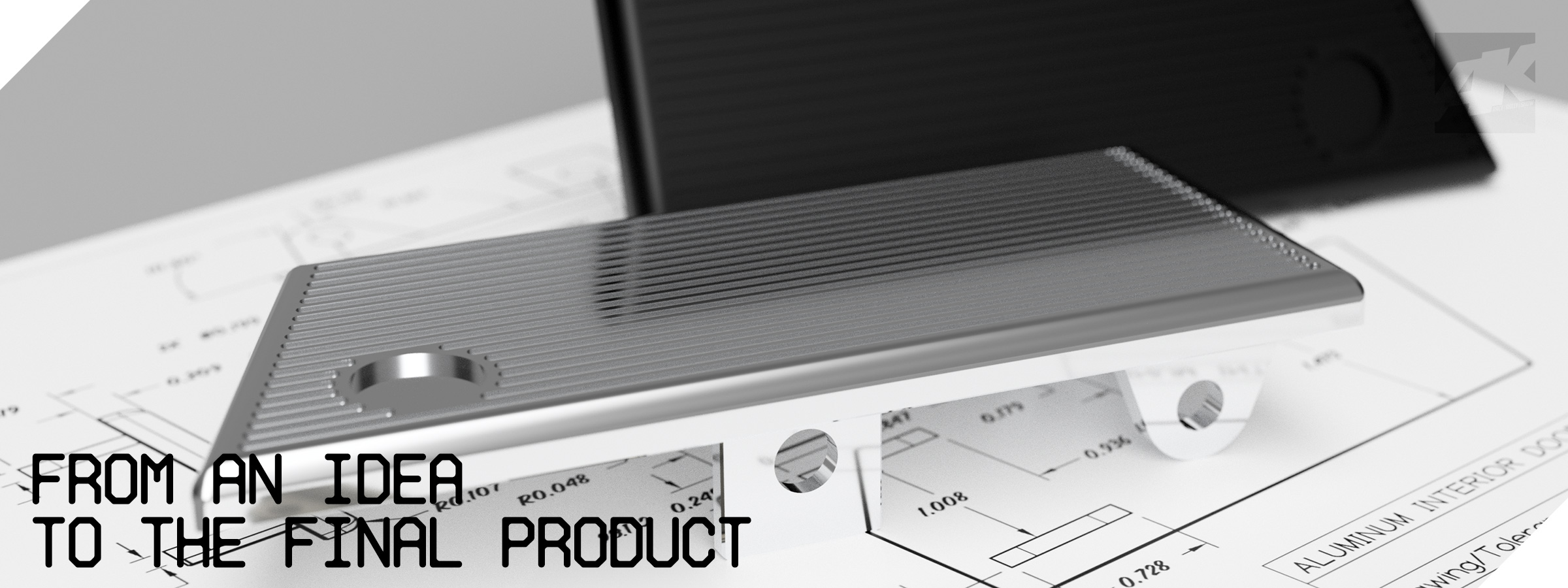
CAD DESIGN
CAD stands for Computer-Aided Design. It refers to the use of computer software to create, modify, analyze, and optimize designs for various products and systems. CAD software allows engineers, architects, designers, and other professionals to generate detailed 2D and 3D models of objects, structures, or components.
CAD design facilitates the visualization of concepts, enabling designers to explore different iterations and variations of a design before committing to physical prototypes. It offers precision and accuracy in measurements, as well as the ability to simulate real-world conditions and performance. Additionally, CAD software often integrates with other tools and technologies, such as computer-aided engineering (CAE) and computer-aided manufacturing (CAM), forming a complete digital design and production workflow.
Overall, CAD design plays a crucial role in modern product development processes, allowing for faster, more efficient, and cost-effective design iterations and ultimately leading to the creation of better-quality products.

CAD FAQ's


3D SCANNING
3D SCANNING PRICING
How much 3D scanning costs is a frequent question of our customers. And it’s a complex one too. Just like with any other technological equipment, many factors need to be considered.
- The size of an object or a part
A larger object will typically require more time and scans to get a complete model than a smaller object. Therefore, a scan of a larger object will cost more than a scan of a smaller object. - Geometry of an object or a part
A larger object will typically require more time and scans to get a complete model than a smaller object. Therefore, a scan of a larger object will cost more than a scan of a smaller object. - Quantity of parts or objects in a project
This consideration logically follows the first two — the more objects or parts you need to capture, the more resources it will take to scan and process them, whether you plan to do it in-house or outsource. Each part of an object, or multiple solid objects, still needs to be scanned on its own and may require a different scanning and data processing workflow.
For example, for a complete scan ready for reverse engineering, the item frequently needs to be disassembled so that each component can be scanned separately. - Accuracy and resolution of a final model
Therefore, the more accurate and high-quality you need your model to be, the more expensive it will be to capture it in 3D. - Color
Another factor that goes into the scanning cost is color. Some applications require color scans and a true likeness of an object. - Application
If you are seeking raw 3D scan data, it usually comes at no additional cost.
If you need to get a parametric CAD model as an output instead of a mesh, this step will cost extra. - Complex materials and scanning condition
Some surfaces that are reflective or shiny can be challenging to capture as is and may require additional time spent on preparation and spraying them with a washable or vanishing scanning spray, as well as the clean-up afterward.
Hourly Rates – Generally, smaller projects are charged an hourly rate of anywhere between $100 – $500.
Daily Rates – Larger projects that require multiple days of scanning may be charged a daily rate of $1,000 – $3,000.
On average, the price ranges from $250 for a simple small object to more than $2,000 for a complex mechanical part.
For example. A car rim 15×6.5 falls under the medium-complexity category and it can cost up to $800 for the job.
Please contact us and we can discuss further your needs for 3D scanning.


SCANNING CAPABILITIES
Measurement accuracy: ±10 μm
Measurement resolution: 9 million points
Captured data format: Full-color textured 3D mesh data
Stage top panel size: ⌀ 500 mm (⌀ 19.69″)
Stage rotation: 360° (infinite rotation)
Stage movement range: ⌀ 200 mm (⌀ 7.87″)
Tilt mechanism: up to 45°
Load capability: 50 kg (110.23 lb)
Measurement range:
Low magnification (wide field) – ⌀ 300 x H 200 mm (⌀ 11.81″ x H 7.87″)
High magnification (high resolution) – ⌀ 70 x H 50 mm (⌀ 2.76″ x H 1.97″)
Extended measurement:
Low magnification (2 × 2 composition) – ⌀ 500 x H 200 mm (⌀ 19.69″ x H 7.87″)
Low magnification (3 × 1 composition) – W 580 x D 300 x H 200 mm (W 22.83″ x D 11.81″ x H 7.87″)*
High magnification (2 × 2 composition) – ⌀ 110 x H 50 mm (⌀ 4.33″ x H 7.97″)
High magnification (3 × 1 composition) – W 150 x D 70 x H 50 mm (W 5.91″ x D 2.76″ x H 1.97″)*
*Largest width for long and circular shape range

